
Before the press power button any laptop has an embedded controller that controlled the trigger.
ENE Keyboard Controller series is a highly integrated embedded controller (EC) for laptop platform.
It appeals for low power consumption and best-in-class performance to satisfy customers’ demand.
ENE Keyboard Controller Functions
The system support functions include 8051 MCU, LPC interface, PS/2 interface, Keyboard matrix encoder, PWM, A/D converter, D/A converter, Fan controller, SMBus interface, GPIO, PECI, one wire master, SPI and ENE Serial Bus.
Here we understand what are the most important points which has to be activated before the press power button.
Before Press Power Button Points to remember
Power for EC
When ENE keyboard controller Provided by the power it active the analog and digital power Section. 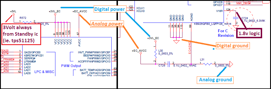
Clock On Clock
 By default, it generates the clock on clock pins (32.768 kHz). If Susclk is used then it provided by intel chipset by RTC section activity and it is in Square waves.
EC Reset or POR#
When Clock is on Clock then Ec reset is taking place. This delay must take place after the clock generation. That is because of the use of the RC circuit used on ECRST#. After ECRST# EC output clock on EC Bios pin no.6 that is usually 12mhz to 30mhz, you can check it by removing bios chip and then check pin6 for clock with DSO and click the power button. This is the signal which makes bios active to input and output data and time selection for chip select signal to read-write operations.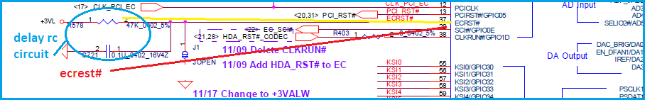
Bios Functionality
 When bios is mounted 3.3v must be there on pin8, pin7and pin3
Pin 8 is for VCC power for bios chip. Pin 7 for hold for pause operations when using a low buffer area. Pin 3 is for write protection for the device. When the clock present on pin6. EC control CS# signal for Data input and output operations. When CS# is High chip is not select for Data input and output when CS# is in low then EC Input and output made. Ec input data for the certain addresses to read from pin5 and output Will make from pin2. Data is generally used in 8 bit.
ACIN Signal
When System Driven by adaptor this signal should be high it recognizes the adaptor ok condition to run the system. It should have 3.3v on this signal.
Note: learn about Power adapter working in laptop

RSMRST# or Resume Reset
This signal must be low or 0v. This signal used to resume suspended power plan logic. It holds the logic until the power button not pressed. This is the third reset for the system.
EC_ON
After successful bios data read this signal should be high on 3.3v. it enables for 3valw and 5valw always standby supply.
On/Off Button
This is on/off logic signal of a system restart. It releases the hold of power plans and resumes reset occurred.
LID Switch or LID_SW#
This is a standby enable signal if this enables (0v). Then internal logic enables sleep or standby signal. So the system always in stand by when this signal is enabled. It should be de-asserted (3.3v on it) when press power button.
Battery data and clock
This is SMBus communication lines which read battery status and charging ic working condition. It should have high logic (3.3v).
I think you understand now this is very important to check these various signal before press power button.
ENE keyboard controller has these basic requirements to start the power-on sequence.
There are many other signals that can be introduced in the future, so we have to study every day every time to upscale our knowledge.
I hope you liked this article, tell me what you think about the ENE keyboard controller process by commenting below.